Published by Christopher J. Holley | Mopar History & Tech | June 2026
Among vintage Mopar enthusiasts, few components are as misunderstood as the voltage regulator. The small box mounted on the firewall is often blamed whenever a battery goes dead, headlights dim, or the ammeter needle starts wandering. Yet the regulator is only one piece of Chrysler’s charging system and understanding how it works can eliminate hours of frustration and prevent unnecessary parts replacement.
The basic job of every charging system is simple. The alternator must produce enough electricity to power the vehicle while simultaneously replenishing the battery. Left uncontrolled, an alternator would continue increasing output as engine speed rises, potentially producing damaging voltage levels. The voltage regulator prevents that from happening by controlling current flowing through the alternator’s rotor field windings.
The stronger the magnetic field inside the rotor, the more electricity the alternator produces. The weaker the magnetic field, the less electricity it generates. The voltage regulator’s sole purpose is to control that magnetic field and maintain system voltage at approximately 13.5 to 15.0 volts.
While that principle remained constant throughout the muscle car era, Chrysler employed two distinctly different charging system designs. The system used through 1969 is known as a B-circuit, while the system introduced in 1970 is known as an A-circuit.
Understanding the difference is the key to diagnosing almost any Mopar charging problem.
The Pre-1970 B-Circuit Charging System
From the early 1960s through the 1969 model year, Chrysler vehicles used a charging system consisting of a single-field alternator and a mechanical voltage regulator.
In a B-circuit system, one side of the rotor field winding is permanently grounded inside the alternator. The voltage regulator controls the positive side of the field circuit by supplying current to the field terminal.
When the regulator applies battery voltage to the field winding, the rotor becomes a stronger electromagnet and alternator output increases. When the regulator reduces field current, alternator output decreases.
The regulator itself is a remarkable electromechanical device. Hidden beneath its cover are electromagnetic coils, springs, resistors, and contact points. As charging voltage rises, magnetic force inside the regulator causes the contacts to open, reducing field current. As voltage drops, the contacts close again, restoring current flow.
This cycle repeats continuously while the engine is running.
Although primitive by modern standards, the system was extremely effective for its day. Millions of Chrysler vehicles accumulated hundreds of thousands of miles using this design.
However, time eventually catches up with every mechanical regulator. Contact points become pitted, springs weaken, and corrosion develops. Since the regulator relies on its mounting screws and firewall connection for grounding, even minor corrosion can affect charging performance.
Many “bad alternators” ultimately turn out to be poor grounds or failing regulators.
For owners of 1968 and 1969 Road Runners, GTXs, Super Bees, Chargers, and Coronets, this is the charging system originally installed by Chrysler.
Chrysler Goes Electronic
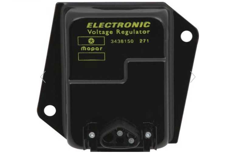
For the 1970 model year, Chrysler engineers introduced one of the most significant electrical improvements of the muscle car era: the electronic voltage regulator.
The change required a redesigned alternator featuring two insulated field terminals instead of one. Together, the new regulator and alternator formed what Chrysler enthusiasts know as the A-circuit charging system.
Unlike the earlier B-circuit design, neither side of the field winding is grounded inside the alternator.
Instead, one field terminal receives ignition voltage whenever the key is on. The electronic regulator controls the ground side of the field circuit by rapidly connecting and disconnecting the field winding from ground.
This seemingly small change eliminated the need for moving contacts and springs. The new regulator used solid-state electronics to control field current far more accurately than the mechanical design it replaced.
The advantages were substantial:
- Faster response to changing electrical loads
- Improved voltage stability
- Elimination of contact wear
- Longer service life
- More reliable charging performance
More than fifty years later, countless original electronic regulators are still functioning.
Why Grounding Matters
One characteristic shared by both systems is their dependence on proper grounding.
The electronic regulator introduced in 1970 senses system voltage through its housing. If rust, paint, corrosion, or loose mounting hardware interferes with the regulator’s ground path, charging problems quickly develop.
The regulator may undercharge, overcharge, or cycle erratically because it is receiving inaccurate voltage information.
Experienced Mopar technicians often begin diagnosis by cleaning regulator mounting surfaces and verifying continuity between the regulator housing and battery negative terminal. In many cases, a dedicated ground wire is added to ensure a reliable connection.
A poor ground can mimic a failed regulator.
Understanding Full-Field Testing
Perhaps the most valuable charging system diagnostic procedure Chrysler ever published is the full-field test.
The purpose is straightforward. When a charging problem occurs, it can be difficult to determine whether the regulator is limiting alternator output or the alternator itself has failed.
Full-fielding temporarily bypasses the regulator and forces the alternator to produce maximum output.
If charging voltage immediately increases, the alternator is capable of doing its job and the problem lies elsewhere.
If voltage does not increase, the alternator itself is likely defective.
Full-Fielding a B-Circuit Alternator (1969 and Earlier)
Because the regulator controls the positive side of the field circuit, the test is performed by applying battery voltage directly to the alternator field terminal.
This bypasses the regulator and fully energizes the rotor field winding.
If charging voltage rapidly climbs above normal operating voltage, the alternator is functioning properly.
Full-Fielding an A-Circuit Alternator (1970 and Later)
Since the regulator controls the ground side of the field circuit, the regulator-controlled field terminal is momentarily grounded.
This completes the field circuit and forces maximum rotor excitation.
Once again, charging voltage should rise rapidly if the alternator is healthy.
In either system, the test should only be performed for a few seconds. A fully excited alternator can produce excessive voltage capable of damaging bulbs, batteries, electronic ignition components, and sensitive accessories.
Testing Voltage Regulator Operation
Diagnosing a Mopar charging system requires only a few basic checks.
Begin with the battery. A fully charged battery should measure approximately 12.6 volts with the engine off.
Next, start the engine and raise speed to roughly 1,500 rpm. A properly functioning charging system should maintain approximately 13.5 to 15.0 volts.
If charging voltage remains near battery voltage, charging output is insufficient. If voltage exceeds approximately 15 volts, overcharging is occurring.
At that point, inspect all charging system connections, paying particular attention to regulator grounding.
If no obvious problems are found, perform a full-field test.
If voltage immediately rises during the test, the alternator is likely healthy and attention should shift to the regulator, field wiring, or ground connections.
If voltage fails to increase, the alternator itself becomes the primary suspect.
Possible alternator faults include:
- Worn brushes
- Open rotor winding
- Damaged stator
- Failed rectifier diodes
- Broken field connections
The Bottom Line
Despite decades of confusion surrounding A-circuits and B-circuits, the distinction is actually simple.
The 1960–1969 Mopar charging system is a B-circuit design. The field winding is internally grounded, and the mechanical voltage regulator controls the positive side of the field circuit.
The 1970-up Mopar charging system is an A-circuit design. The field winding is isolated from ground, and the electronic voltage regulator controls the ground side of the field circuit.
Both systems accomplish the same task: regulating alternator output by controlling rotor field current.
For anyone restoring a 1968 Hemi Road Runner, that means understanding the operation of the original B-circuit mechanical regulator is every bit as important as understanding the alternator itself. More often than not, charging system problems are not caused by a bad alternator at all. They are caused by poor grounds, aging regulators, corroded connections, or a misunderstanding of how the system actually works.
As countless Mopar technicians have learned over the years, the fastest path to the truth is often a simple voltmeter, a good ground connection, and a properly performed full-field test.


Leave a Reply